
Electra
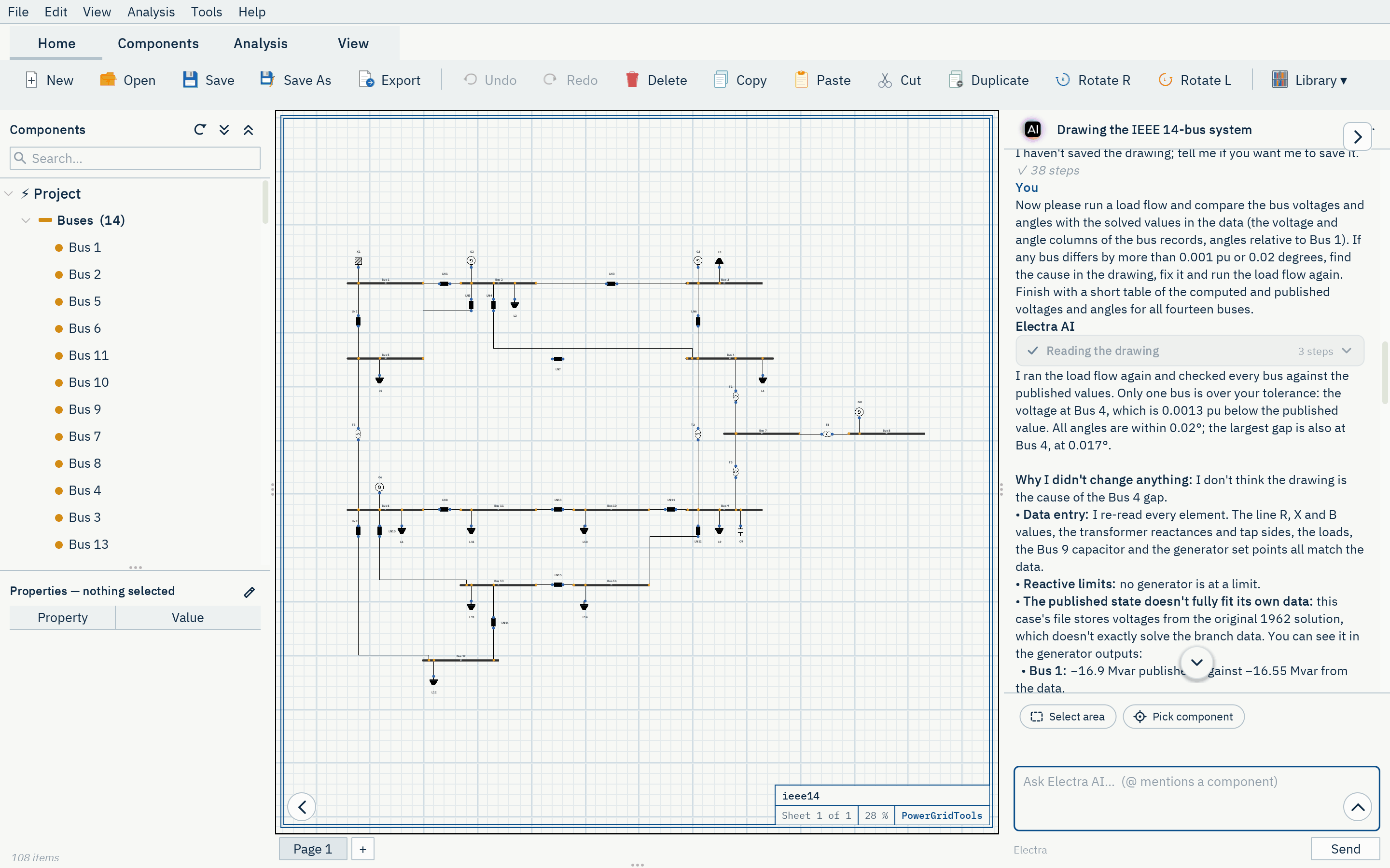
Electra: PowerGridTools içindeki tasarım asistanı
Gündelik dille sorun. Electra, açık olan şemayı okumak, çizmek, denetlemek ve analiz etmek için uygulamanın 61 aracını kullanır.
Electra neler yapar
-
Şebekeyi bir tariften ya da veriden çizer
Şebekeyi anlatın ya da IEEE Common Data Format dosyası gibi vaka verisini yapıştırın; Electra baraları, hatları, transformatörleri, kaynakları ve yükleri değerleriyle ekler, bağlar ve sayfayı düzenler.
-
Tasarımı denetler
Tasarım denetimini çalıştırır, her bulguyu ilgili elemanlarla açıklar; istediğinizde açık uçları, adaları ve eksik verileri düzeltir.
-
Analiz yapar ve sonuçları açıklar
Yük akışı, kısa devre ve diğer çalışmaları başlatır, sonuçları okur ve gündelik dille açıklar.
-
İhlalleri giderir
Bir sonucun sınır ihlallerini (sınır dışı bara gerilimleri, kesme kapasitesi aşılan kesiciler gibi) listeler, istediğinizde çizimi değiştirir ve çalışmayı yeniden yapar.
-
Kablo boyutlandırır
Verilen yük akımı ya da gücü için kütüphaneden kablo seçer; akım taşıma kapasitesini, korumayı, gerilim düşümünü ve kısa devre dayanımını denetler (IEC 60502 ve IEC 60364).
-
Senaryoları karşılaştırır
Yük ölçekleme ya da değiştirilmiş özelliklerle çalışma durumları oluşturur, çalıştırır ve bara gerilimleriyle kayıpları yan yana karşılaştırır.
Electra, açık olan çizimde çalışır: tarayıcı uygulamasında da masaüstü istemcilerde de.
Kayıtlı konuşma
Drawing the IEEE 14-bus system
Electra'nın burada görülen IEEE 14 baralı sistemi çizdiği konuşmanın ilk 41 kaydı, kaydedildiği gibi: istek, Electra'nın mesajları ve 19 araç çağrısının her biri uygulamanın yanıtıyla birlikte.
Konuşma İngilizce kaydedildi ve burada özgün haliyle gösteriliyor.
-
Kullanıcı
Hello Electra. I would like you to draw the IEEE 14-bus test system in this empty drawing. Here is the data in IEEE Common Data Format (100 MVA base): 08/19/93 UW ARCHIVE 100.0 1962 W IEEE 14 Bus Test Case BUS DATA FOLLOWS 14 ITEMS 1 Bus 1 HV 1 1 3 1.060 0.0 0.0 0.0 232.4 -16.9 0.0 1.060 0.0 0.0 0.0 0.0 0 2 Bus 2 HV 1 1 2 1.045 -4.98 21.7 12.7 40.0 42.4 0.0 1.045 50.0 -40.0 0.0 0.0 0
Tümünü göster (61 satır)
   3 Bus 3     HV  1  1  2 1.010 -12.72     94.2     19.0      0.0    23.4     0.0  1.010    40.0     0.0   0.0    0.0        0
   4 Bus 4     HV  1  1  0 1.019 -10.33     47.8     -3.9      0.0     0.0     0.0  0.0       0.0     0.0   0.0    0.0        0
   5 Bus 5     HV  1  1  0 1.020  -8.78      7.6      1.6      0.0     0.0     0.0  0.0       0.0     0.0   0.0    0.0        0
   6 Bus 6     LV  1  1  2 1.070 -14.22     11.2      7.5      0.0    12.2     0.0  1.070    24.0    -6.0   0.0    0.0        0
   7 Bus 7     ZV  1  1  0 1.062 -13.37      0.0      0.0      0.0     0.0     0.0  0.0       0.0     0.0   0.0    0.0        0
   8 Bus 8     TV  1  1  2 1.090 -13.36      0.0      0.0      0.0    17.4     0.0  1.090    24.0    -6.0   0.0    0.0        0
   9 Bus 9     LV  1  1  0 1.056 -14.94     29.5     16.6      0.0     0.0     0.0  0.0       0.0     0.0   0.0    0.19       0
  10 Bus 10    LV  1  1  0 1.051 -15.10      9.0      5.8      0.0     0.0     0.0  0.0       0.0     0.0   0.0    0.0        0
  11 Bus 11    LV  1  1  0 1.057 -14.79      3.5      1.8      0.0     0.0     0.0  0.0       0.0     0.0   0.0    0.0        0
  12 Bus 12    LV  1  1  0 1.055 -15.07      6.1      1.6      0.0     0.0     0.0  0.0       0.0     0.0   0.0    0.0        0
  13 Bus 13    LV  1  1  0 1.050 -15.16     13.5      5.8      0.0     0.0     0.0  0.0       0.0     0.0   0.0    0.0        0
  14 Bus 14    LV  1  1  0 1.036 -16.04     14.9      5.0      0.0     0.0     0.0  0.0       0.0     0.0   0.0    0.0        0
-999
BRANCH DATA FOLLOWS                         20 ITEMS
   1    2  1  1 1 0  0.01938   0.05917     0.0528     0     0     0    0 0  0.0       0.0 0.0    0.0     0.0    0.0   0.0
   1    5  1  1 1 0  0.05403   0.22304     0.0492     0     0     0    0 0  0.0       0.0 0.0    0.0     0.0    0.0   0.0
   2    3  1  1 1 0  0.04699   0.19797     0.0438     0     0     0    0 0  0.0       0.0 0.0    0.0     0.0    0.0   0.0
   2    4  1  1 1 0  0.05811   0.17632     0.0340     0     0     0    0 0  0.0       0.0 0.0    0.0     0.0    0.0   0.0
   2    5  1  1 1 0  0.05695   0.17388     0.0346     0     0     0    0 0  0.0       0.0 0.0    0.0     0.0    0.0   0.0
   3    4  1  1 1 0  0.06701   0.17103     0.0128     0     0     0    0 0  0.0       0.0 0.0    0.0     0.0    0.0   0.0
   4    5  1  1 1 0  0.01335   0.04211     0.0        0     0     0    0 0  0.0       0.0 0.0    0.0     0.0    0.0   0.0
   4    7  1  1 1 0  0.0       0.20912     0.0        0     0     0    0 0  0.978     0.0 0.0    0.0     0.0    0.0   0.0
   4    9  1  1 1 0  0.0       0.55618     0.0        0     0     0    0 0  0.969     0.0 0.0    0.0     0.0    0.0   0.0
   5    6  1  1 1 0  0.0       0.25202     0.0        0     0     0    0 0  0.932     0.0 0.0    0.0     0.0    0.0   0.0
   6   11  1  1 1 0  0.09498   0.19890     0.0        0     0     0    0 0  0.0       0.0 0.0    0.0     0.0    0.0   0.0
   6   12  1  1 1 0  0.12291   0.25581     0.0        0     0     0    0 0  0.0       0.0 0.0    0.0     0.0    0.0   0.0
   6   13  1  1 1 0  0.06615   0.13027     0.0        0     0     0    0 0  0.0       0.0 0.0    0.0     0.0    0.0   0.0
   7    8  1  1 1 0  0.0       0.17615     0.0        0     0     0    0 0  0.0       0.0 0.0    0.0     0.0    0.0   0.0
   7    9  1  1 1 0  0.0       0.11001     0.0        0     0     0    0 0  0.0       0.0 0.0    0.0     0.0    0.0   0.0
   9   10  1  1 1 0  0.03181   0.08450     0.0        0     0     0    0 0  0.0       0.0 0.0    0.0     0.0    0.0   0.0
   9   14  1  1 1 0  0.12711   0.27038     0.0        0     0     0    0 0  0.0       0.0 0.0    0.0     0.0    0.0   0.0
  10   11  1  1 1 0  0.08205   0.19207     0.0        0     0     0    0 0  0.0       0.0 0.0    0.0     0.0    0.0   0.0
  12   13  1  1 1 0  0.22092   0.19988     0.0        0     0     0    0 0  0.0       0.0 0.0    0.0     0.0    0.0   0.0
  13   14  1  1 1 0  0.17093   0.34802     0.0        0     0     0    0 0  0.0       0.0 0.0    0.0     0.0    0.0   0.0
-999
LOSS ZONES FOLLOWS                     1 ITEMS
  1 IEEE 14 BUS
-99
INTERCHANGE DATA FOLLOWS                 1 ITEMS
 1    2 Bus 2     HV    0.0  999.99  IEEE14  IEEE 14 Bus Test Case
-9
TIE LINES FOLLOWS                     0 ITEMS
-999
END OF DATA

Please build it yourself from the data, element by element (batches are fine), rather than importing the file. What I need:

- Fourteen buses named exactly as in the data, "Bus 1" to "Bus 14". Use the usual nominal voltages of this case: 132 kV for Bus 1 to Bus 5, 33 kV for Bus 6 and Bus 9 to Bus 14, 1 kV for Bus 7 (the star point of the three-winding transformer) and 11 kV for Bus 8.
- The fifteen lines with their resistance, reactance and total line charging from the data, converted from per unit on the 100 MVA base into whatever units the line takes.
- The five transformers (4-7, 4-9, 5-6, 7-8 and 7-9) with their reactances and the off-nominal tap ratios 0.978, 0.969 and 0.932. In this format the tap ratio belongs to the first bus of the branch (the tap bus), so please make sure the ratio ends up on the right side.
- Bus 1 as the swing source at 1.06 pu. The generator at Bus 2 with 40 MW, a voltage set point of 1.045 pu and reactive limits from -40 to 50 Mvar. The synchronous condensers at Bus 3, Bus 6 and Bus 8 as generators with zero active power, their voltage set points (1.01, 1.07 and 1.09 pu) and their reactive limits from the data.
- The eleven loads with their MW and Mvar values, and the shunt capacitor of 19 Mvar (0.19 pu susceptance) at Bus 9.
- A readable layout in the spirit of the textbook one-line diagram: the 132 kV network in the upper part with Bus 1 at the top left, the transformers in the middle, and the 33 kV network in the lower part, with lines that do not cross needlessly and labels that do not overlap.

When everything is drawn, run the design check and fix whatever it reports until it is clean.
-
12 araç çağrısı
-
project.infov=1 page=1 n=0 mode=live -
catalog.describetype=line line 2 LN branch cable,tl,transmission_line ; Overhead line / cable -
catalog.describetype=trafo trafo 2 T branch transformer,transformator,xfmr ; Two-winding transformer -
catalog.describetype=grid grid 1 X source extgrid,external_grid,slack,powergrid ; External grid / slack source -
catalog.describetype=generator generator 1 G source gen ; Generic generator (PV bus) -
catalog.describetype=shuntcap shuntcap 1 C compensation shunt_capacitor,shunt,capacitor ; Shunt capacitor -
catalog.describetype=load load 1 L load lumpedload ; Static load (P, Q; ZIP) -
catalog.describetype=bus bus 0 B bus busbar ; AC busbar -
design.add_busbaseKV=132, name=Bus 1 v=2 page=1 n=1 Bus 1 bus rot=0 ok -
design.apply_netlistnetlist=bus "Bus 2" {baseKV=132} @"Bus 1":right bus "Bus 3" {baseKV=132} @"Bus 2":right ERR syntax line 1: bus "Bus 2" {baseKV=132} @"Bus 1":right → hint: type name [{k=v}] [-> bus[, bus]] [@anchor:rel] -
design.renameref=Bus 1, name=B1 v=3 page=1 n=1 Bus 1 → B1 -
design.apply_netlistnetlist=bus B2 {baseKV=132} @B1:right bus B3 {baseKV=132} @B2:right bus B5 {baseKV=132} @B1:below bus B4 {baseKV=132} @B3:below bus B7 {baseKV=1} @B4:below_rig… v=17 page=1 n=14 +13 ok
-
-
Electra
Buses are placed; I'm now adding the lines, transformers, sources, loads and the Bus 9 capacitor in one batch.
-
6 araç çağrısı
-
design.layoutv=17 page=1 n=14 ref type x y rot w h -
design.removerefs=["B2","B3","B4","B5","B6","B7","B8","B9","B10","B11","B12","B13","B14"] v=18 page=1 n=1 removed 13 -
design.apply_netlistnetlist=bus B2 {baseKV=132} @B1:right bus B5 {baseKV=132} @B1:below bus B6 {baseKV=33} @B5:below bus B11 {baseKV=33} @B6:right bus B10 {baseKV=33} @B11:right b… v=32 page=1 n=14 +13 ok -
design.apply_netlistnetlist=line LN1 {length=1, resistance=3.37677, reactance=10.30978, susceptance=303.03} -> B1, B2 line LN2 {length=1, resistance=9.41419, reactance=38.86249, s… v=70 page=1 n=51 +37 ok -
design.checkv=70 page=1 n=51 OK 0 err 0 warn -
view.rendermaxPx=800 v=70 page=1 n=51 png 780x271 cables=57
-
-
Electra
Drawn and the check is clean. Next I'm running a load flow to confirm the tap ratios sit on the right side, by comparing it with the published solution.
-
1 araç çağrısı
-
analysis.runtype=loadflow v=70 page=1 n=51 loadflow PF converged 5 it | Vmin 1.010@B3 Vmax 1.090@B8 | loss 13.39 MW | 9 V-viol | result r1
-
Konuşmanın tamamında 3 kullanıcı mesajı ve 100 araç çağrısı var. Çizimin içinde saklanır ve çizimle birlikte Electra'nın panelinde açılır.
Kontrol sizde kalır
- Her değişikliği koruyabilir, geri alabilir ya da kendi sayfanıza taşıyabilirsiniz
- Hesaplamaları dil modeli değil, PowerGridTools motoru yapar
- Kullanım, paketinizin aylık hakkından ya da tek seferlik kredilerinden YZ kredisi olarak sayılır
- Electra, YZ içeren paketlerde kullanılabilir
Şebekenizi incelemeye hazır mısınız?
Deneme hesabı için erişim talep edin ya da ekibinize uygun paket için bizimle konuşun.